Su carrito de compras está vacío
 
English Polski Spanish 
Buscar un manual
 

(p.Ej. AA-V20EG JVC, ZX-7 Sony)
PayPal 1000+ rating Secure, Encrypted Checkout.
 
Usuarios conectados
Actualmente hay 5687 visitantes online.
Productos
Información
Destacado
Inicio >> HITACHI >> CPX327 Manual de Servicio
 
 0 artículo(s) en Su carrito 

HITACHI CPX327
Manual de Servicio


¡Twitee acerca de este producto y obtenga $1.00 de crédito en la tienda para uso!
  • Contiene diagramas del circuito
  • Descargable
  • Formato PDF
  • Manual completo
  • Idiomas: English
Precio: $4.99

Descripción del HITACHI CPX327 Manual de Servicio

Manual de servicio completo en formato digital (archivo PDF). Los manuales de servicio por lo general contienen diagramas de circuitos, tarjetas de circuitos impresos, consejos para reparación, diagramas de cableado, diagramas de bloque y lista de refacciones. El Manual de Servicio (a veces llamado Manual de Reparación) es usado principalmente por los técnicos.

Si tan solo quiere saber cómo utilizar su televisión, reproductor de vídeo, reproductor de mp3, etc. Quizá lo que necesita es el Manual del Propietario. Después de colocar la orden le enviaremos las instrucciones de descarga a su dirección de e-mail.

The manual is available in languages: English

Not yet ready
You must purchase it first

Opiniones de los clientes
No hay comentarios de productos.

TEXT_PDF_SNIPPET
1pin

2-8pin J2

FEB3 9-14pin Sensor board

CNPOW

J1

34

9. Wiring diagram

Wiring for Circuit Power Supply and Ballast Power Supply Boards
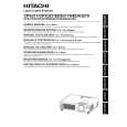
Wiring for Circuit Power Supply Board (1) Keep a record of the circuit power supply lot number in the 100% inspection record. (2) Connect the TSW. (3) Install the FEB3. (4) Connect the CNPOW. (5) Connect the CNTH. (6) Apply the TAP3. CN104 CN102 CN101 TSW Pass the leads through the board holder notch. Connect the CNPWR to connector J1 then make sure that the CNPWR is completely locked. Connect the FEB3 (ferrite core) to pins 2-8 of the CNPOW. Make sure that the CN102 and the CN104 have been securely connected (since they cannot be checked in subsequent processes). Install the sensor board after completing the following steps: Connect the CNTH to connector E950 on the sensor board. E950 Sensor board Make sure that connector E950 has been securely connected then apply the TAP3 (to prevent detachment). Perforation Cut off the sheet by bending it back and forth 2 or 3 times. Wiring for Ballast Power Supply Board (1) Keep a record of the ballast power supply lot number in the 100% inspection record. (2) Cut off the PVC sheet. (3) Connect the CNPWR. (4) Install the FEB2. (5) Connect the CNBAR. (6) Install the ballast shield (in accordance with the general assembly drawing). Connect the FEB2 (ferrite core) to the CNPWR then move the CNPWR to the connector as illustrated below: FEB2

CNPWR

CNBAR

Connect the CNBAR to connector J2, while holding down the small board mounted with the J2 (to prevent stress on the small board).

Cut off the PVC sheet by bending it back and forth 2 or 3 times with your hand, while holding down the double-coated adhesive tape affixed to the igniter transformer so the tape cannot come off. Igniter transformer

CNTH

TAP3

Quizás también quiera comprar

$4.99

CPX327 HITACHI
Manual de Usuario

Manual del propietario completo en formato digital. El manual estará disponible para descarga como …
>
Parse Time: 0.138 - Number of Queries: 100 - Query Time: 0.033